- System Overview
- Creating a Mount for the AUT
- How to Perform a Measurement
- Generating Calibration Files
- Resources
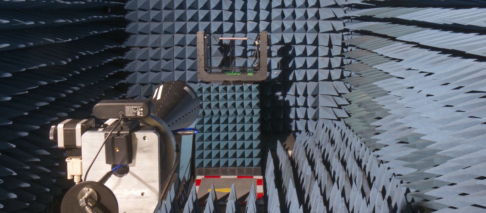
System Overview
The microwave anechoic chamber supports S/C/X/Ku-band operation (2 GHz–18 GHz), enabling accurate radiation pattern and gain measurements in a controlled free-space environment. The antenna-under-test (AUT) is mounted on a positioner system (mmWave Test Solutions) with fine angular control along the θ and φ axes, enabling 3D pattern measurement capabilities.
- Frequency of operation: 2 GHz – 18 GHz
- Coaxial cable for AUT: 2.92 mm
- Maximum weight (antenna + mount): 30 kg
To help plan measurements, consider the following approximate measurement times assuming 1° angular resolution and 101 frequency points. Actual measurement duration may vary depending on software parameters and setup.
- Single 2D Cut: 5-10 min
- 3D Pattern: 2+ hr
Creating a Mount for the AUT
Introduction
There are 2 options for mounting the AUT to the positioner:
- The AUT is mounted onto an existing stainless steel jig that interfaces with the positioner system (recommended). This approach minimizes the amount material needed for producing the mount and results in a more rigid and stable structure. The jig also makes it easy to mount/dismount the AUT.
- Mount the AUT directly onto the positioner platform. This option should only be considered if the AUT is heavy and the combination of that with the jig would surpass the 30 kg limit, or, if the jig interferes with the space required to mount the AUT.
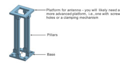
Generally, the mount should consist of 3 parts:
- Base with screw holes (unthreaded) to mount the AUT onto the antenna positioner
- Pillars to hold the AUT at a particular height
- Platform for the AUT to sit on
Mount Design: Option #1 (Recommended)
The recommended screw hole dimensions and spacings (in mm) are shown in the image below:
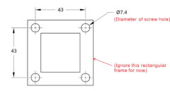
The antenna may be oriented in any desired configuration. However, it must be positioned such that its physical center is located at a height of 304.8 mm (1 ft) above the positioner platform. This ensures proper alignment with the positioner’s center of rotation. Due to the added height from the stainless steel jig, the mount needs to hold the AUT 147 mm above the jig. While it does not have to be exact, the antenna should be positioned as close to this height as possible, especially if the user is planning to perform measurements in various cuts or perform a 3D pattern measurement.
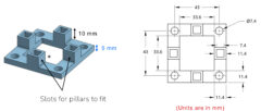
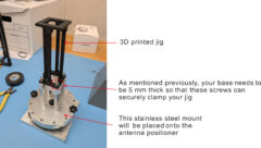
It is important that the base is around 5 mm-thick to ensure that it may be held securely by the jig. It is also a good idea to add slots in the base for pillars to fit to provide extra support for the pillars. See this example:
This is an example of the overall (assembled) mount:
Please see the Resources section for sample 3D model files.
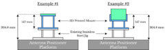
Mount Design: Option #2
The same information discussed for option #1 applies here, except for the following modifications:
- The height of the pillars used to support the AUT must be modified accordingly to account for the lost height which the stainless steel jig provided. Recall, the AUT must be phyiscally centred 304.8 mm above the positoner platform.
- The screw hole diameter should be 5.35 mm
- The screw hole spacing should be 40.65 mm (centre to centre)
How to Perform a Measurement
Step 1: Set up the antenna to be measured onto the positioner.
Step 2: Set the polarization of the measurement by aligning the receiving horn antenna accordingly.
Step 3: Open the anechoic chamber software to run the measurement.
Step 4: Post Processing (Obtain the gain).
The raw measured data is based on the S21 readings from a VNA. To convert this data to gain (dB), download the latest gain calibration file from our GitHub repository. In the GitHub repo, calibration files are listed with the corresponding date they were generated. Use the most recent file for calibration.

Each calibration (.csv) file contains four columns of data obtained from measurements of a known, standard horn antenna: (1) Frequency, (2) Peak S21 measured at broadside, (3) Corresponding gain at that frequency (from the datasheet), and (4) Offset between gain and peak S21, calculated as: Offset (dB) = Gain (dB) – Peak S21 (dB).
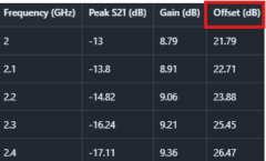
To convert your measured S21 values to gain, use the “Offset (dB)” column with this formula:
Gain (dB) = S21 (dB) + Offset (dB)
For example, to convert measured S21 data to gain at 2 GHz, add 21.79 dB to all measurements at that frequency. Similarly, to obtain the gain pattern at 2.4 GHz, add 26.47 dB to all measurements at that frequency.
Note: The calibration files are generated using an input power of 0 dBm. If a different input power is used during measurement, the measured data must be adjusted accordingly. For example, if an input power of -10 dBm is used, an additional 10 dB should be added in the gain conversion calculation.
Generating Calibration Files
- Mount a standard horn antenna as the antenna under test (AUT) on the positioner and measure its radiation pattern, ensuring that the main beam is fully captured
- The horn antenna typically used for this calibration is the RCDLPHA2G18 by RF-Lambda.
- Settings typically used in the software:
- Frequency Range: 2 GHz – 18 GHz
- Number of Points: 51 or 101
- Input power: 0 dBm
- Extract the peak S21 for each frequency.
- Using the corresponding gain values from the horn antenna datasheet, calculate the calibration offset for each frequency as: Offset (dB) = Gain (dB) – Peak S21 (dB).This MATLAB script automates this process.